Exposure settings
To edit the settings, select an instrument and connect the guider camera with the  button.
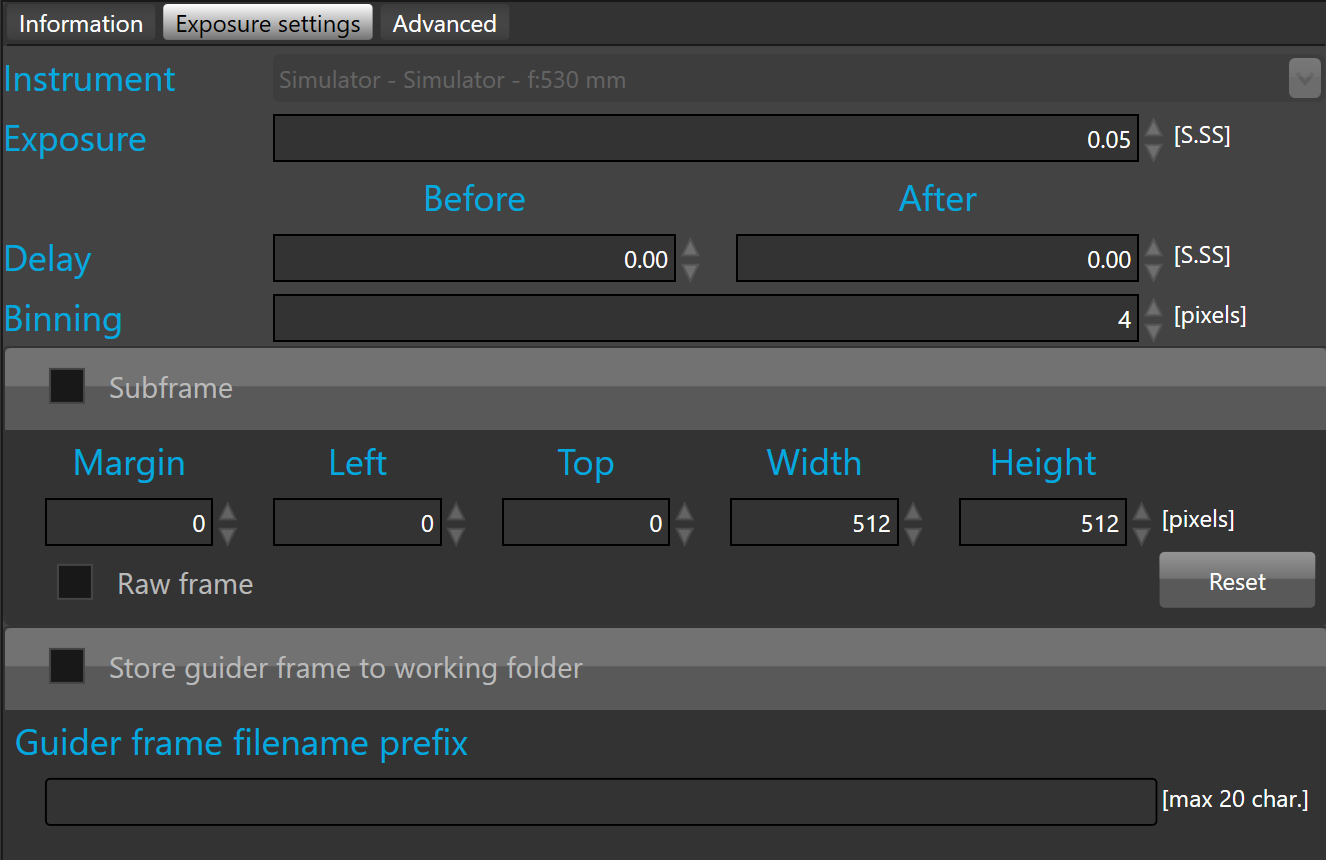
Initially an exposure time must be defined. By default, the exposure time is 3 seconds.
 To minimize the seeing induced auto-guiding errors and for increasing the SNR one strongly advices against using too short guidier exposure values. The best course of action should be to use the longest guider exposure that one can afford for a given mount and setup before drifts become the major limitation. Also aggressiveness values should be set when feasible below 50%, or even less.
Optionally, a delay can be defined before and after exposing with the guider camera. By default, there is no delay.
The pixel binning parameter must be set to 1 to acquire the guider camera images at full resolution.
If binning is set to 2 or more, the resolution will be reduced, but pixel sensibility will be increased and image transfer time will be reduced between the camera and the computer.
Additionally, frame processing time will be reduced.
By default, the binning is set to 2x2.
 With full frame guiding, the guider pixel resolution is not supper critical. SkyGuard processing accuracy is a 10th of the binned guider pixel size supporting large binning values when necessary. Therefore binning by a factor of 4, or more is possible. When larger hardware binning values are not possible anymore SkyGuard will automatically switch to software binning for reaching the requested binning value.
Sub-frame
Guider output frame can be cropped as a sub-frame.
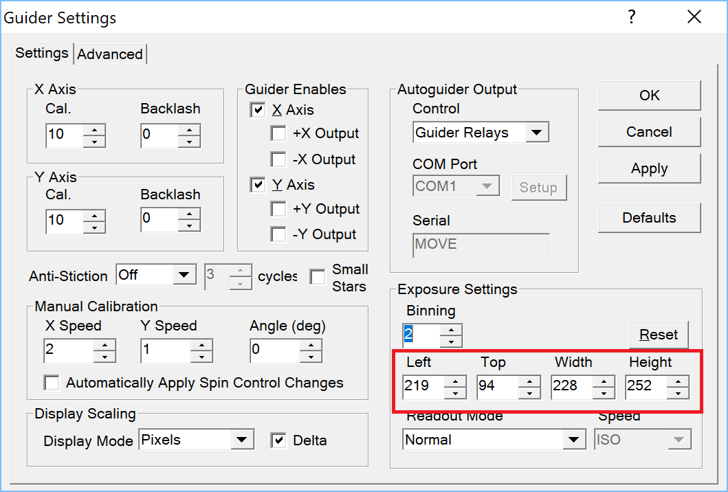
When using ASCOM or MaxIm DL 6, SKG is able to send the crop window to the guider camera in order to crop the guider frame inside the camera prior sending it to the PC.
![]() Some MaxIm DL 5 versions do not support sub-frames, therefore when MaxIm DL 5 is installed this option is disabled. To work with sub-frames in MaxIm DL 6, you must define it in MaxIm DL's guider settings.
Some MaxIm DL 5 versions do not support sub-frames, therefore when MaxIm DL 5 is installed this option is disabled. To work with sub-frames in MaxIm DL 6, you must define it in MaxIm DL's guider settings.
Sub-frame can be defined with a crop margin or a crop window. By default a margin of 20 pixels is defined.
Crop margin offers an easy way to remove patterns that can appear at the border of some guider camera.
Crop window can be defined by editing the value of Left, Top, Width and Height fields but it can also defined interactively on the guider output view port.
To crop interactively, click the ![]() button.
button.
By default, the frame displayed in the camera output is pre-processed by the SKG algorithms. To display the guider output raw frame, just check the raw frame check box.
![]() A guider frame exceeding a megapixel cannot be pre-processed, in that case the raw frame will be displayed instated even if the raw frame check box is not checked.
A guider frame exceeding a megapixel cannot be pre-processed, in that case the raw frame will be displayed instated even if the raw frame check box is not checked.
Once clicked, SKG will capture a new frame from the guider camera and automatically activate the camera output view port and the tool that allow to define the crop window.
To define the crop window, you must right click on the camera output view port, hold the mouse down and move it to define the crop rectangle.
Once the crop rectangle looks like what you expected, just release the mouse button to confirm.
To redefine a new crop window, just right click on the camera output and draw a new rectangle.
Once the crop window is defined the Left, Top, Width and Height fields are updated with the rectangle Left, Top, Width and Height.

The red rectangle will be the sub-frame.
To crop the guider frame with the defined sub-frame, enable the subframe check box.
Store guider frame to working folder
Each guider output frame can be stored to the working folder.
They are automatically named and numbered by SKG.
The name is generated according the following naming convention:
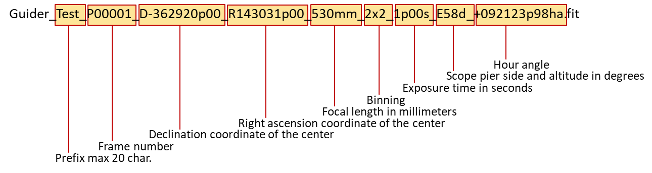
To customize the name, type a prefix with a maximum of 20 characters.
To store guider frames, check the “Store guider frame to working folder” checkbox.
![]() Before storing guider frames to the local hard drive you must check the available space is large enough to store all frames that will be captured during a capture session.
Before storing guider frames to the local hard drive you must check the available space is large enough to store all frames that will be captured during a capture session.